Pressure Pins
Guide to placing pressure pins in a JigsApp project.
Categories:
2 minute read
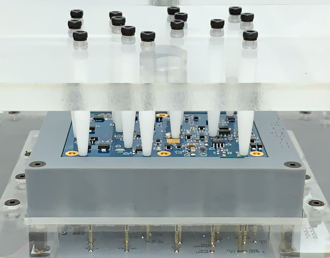
Pressure pins are used on single-sided probing jigs to evenly compress the board into the cradle. It is important that enough pins are used and they’re distributed evenly enough to prevent bending of the DUT. We used Delrin (POM) pins which are hard wearing and self lubricating. The pressure pins are mounted to the pressure plate with screws.
Specifications
- Available Lengths: 10-50mm in 5mm increments
- Sizes: Our standard size has a 6mm top diameter, an M3 threaded hole, and a tapered 3mm diameter point
- Material: Delrin/POM
- Mounting Type: Threaded
Placement Guide
- The number of pins needed depends mostly on the spring force on the DUT. The usual answer is “as many as will conveniently fit”, but you should look to have at least two pressure pins per square inch and no fewer than 6 per board.
- Pressure pins should contact the surface of the board instead of contacting components
- The distribution of pins should be roughly even
- Have pins on the outside of the DUT to minimize tipping
- Pins can overhang the DUT outline in case the edge is the only convenient place but reliefs should be added to the clearance layer to accommodate. This is a good application of the programmatic placement of clearance layer reliefs and the overhanging pressure pins using the design file spreadsheet.
- If there aren’t enough positions free to place the pins, you may need to use a two-cradle configuration with a compressible material instead of pressure pins.
Design Entry
Pressure pins can be added to your design in one of two ways:
- Gerber file: With this method a new layer is made in the EDA design and circles matching the pins diameter are placed at the desired positions. This allows the designer to visualize the placement and make sure the chosen space is free of components. If your EDA system includes a courtyard layer this can be used to prevent collisions.
- Design file: Add a sheet name named “pressure pins” to the design file with the x, y coordinates desired. These will be combined with the gerber file entry if it is there. The generated SVG can be imported into your EDA program to double check your placement is as desired.
The design file method is useful for situations like probing the assembled layer of a single sided load. In that case the pressure pin side is essentially featureless and it is simpler to place the pins programmatically.