Support & Alignment Pins
Categories:
2 minute read
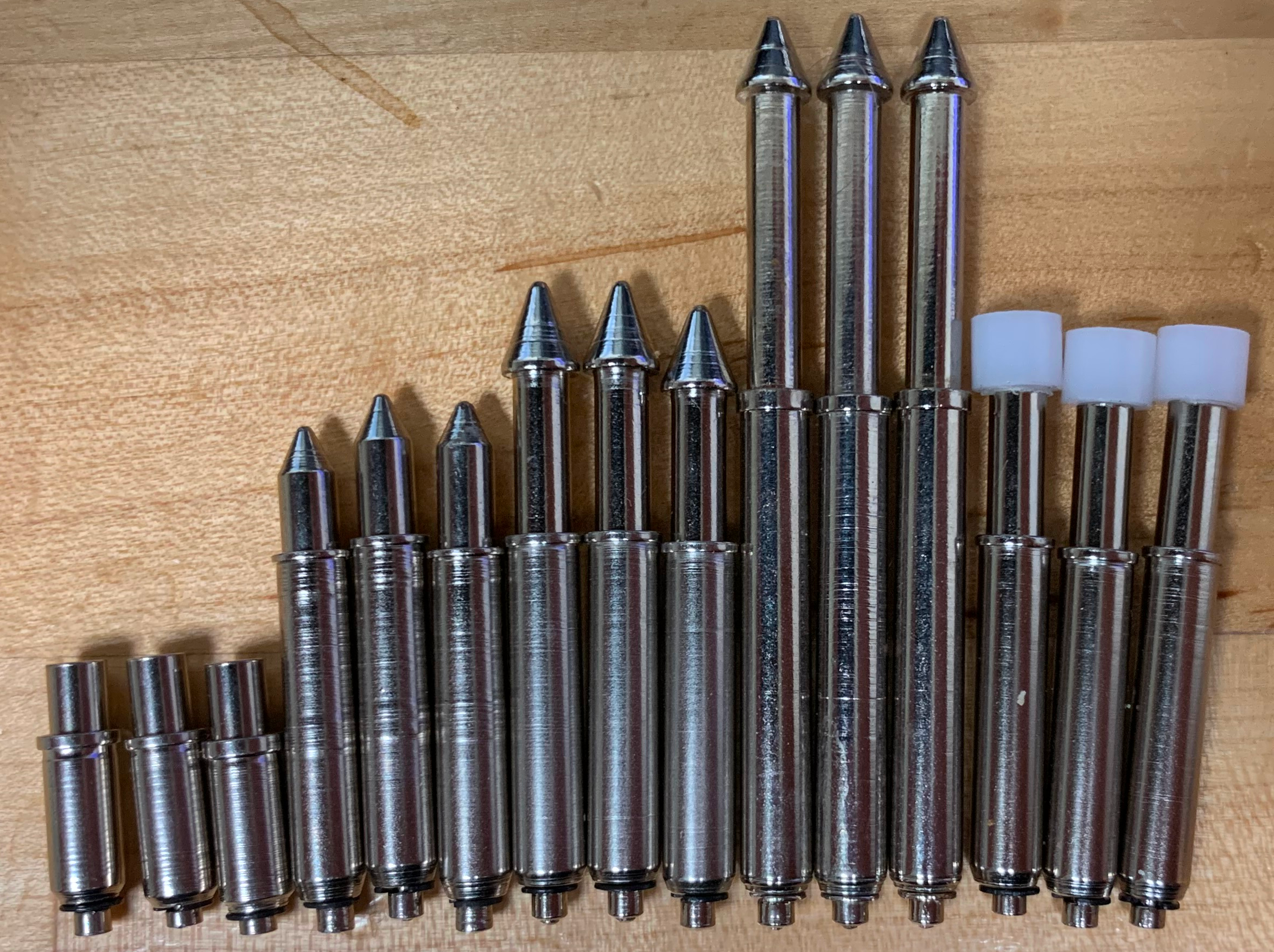
Support pins and alignment pins are used to maintain angular alignment of the DUT in the cradle. Alignment pins also position the DUT in x, y, & θ by picking up mounting holes. The clearance layer of our cassettes provide the transverse alignment in the absence of mounting holes.
Placement Guide
The easiest way to build a jig is with a (roughly) rectangular board with symmetrical mounting holes in all four corners. Those holes are picked up with alignment pins and no cradle clearance layer is needed. For the designs that don’t follow that exact prescription we use support pins which contact an exposed section of the DUT’s PCB. Three points distributed with the boards center of mass between them is sufficient to maintain the DUTs position while it is being compressed into the cradle.
We offer a variety of support and alignment pins which are specified in your project. The mounting structure is identical for the same class of support pins making experimentation simple in case your board’s shape is challenging.
Design Entry
- Add a sheet name named “hardware” to the design file with the x, y, & z coordinates desired.
classis an optional field that sets the mounting feature type. If this is not set then the class defaults to the standard GP-2 class. Which fits a wide variety of standard supports. The height does differ between varieties so you should plan out the type you want to use before hand. We can help if needed!- The generated SVG can be imported into your EDA program to double check that everything lines up.